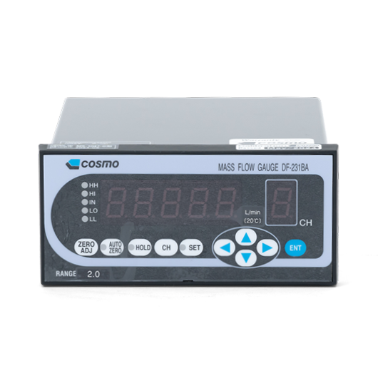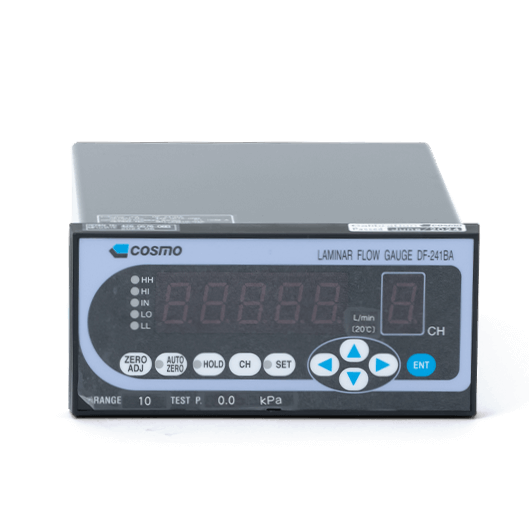
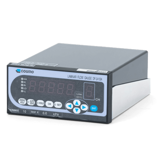
DF-241BA Flow Gauges
- Wide measurement ranges
- High accuracy
- Laminar flow
- Captures instantaneous flow with high responsiveness. Flowmeter for production lines that require flow test and leak test.
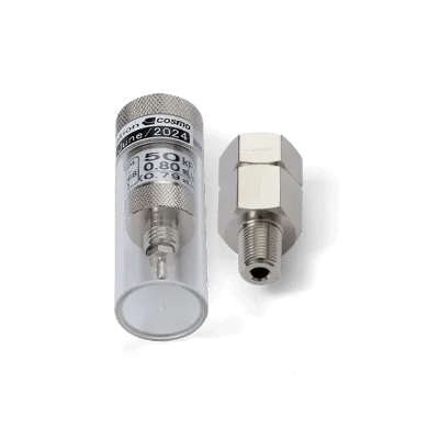
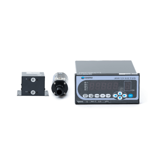
The set includes a flow sensor (laminar flow tube), a differential pressure sensor, and a multi-function indicator.
Basic Specs.
| Pressure range | -70 kPa to 990 kPa (depending on the range of laminar flow tube) |
|---|---|
| Flow range | 10 mL/min to 500 L/min |
| Power source voltage | 24 VDC ± 10%, 0.3 A max |
| Ambient temperature | Operating temperature: +5 to +35℃ |
| External dimensions | W140 x D172 x H66 (Display) |
| Panel cut | Cutting dimensions: W133 x H61 |
Features / Functions
Features
- Measures air flow with high accuracy of ±2% of F.S.
- High responsiveness by using laminar flow tube.
- Suitable for various flow ranges.
- Stability and durability with high-accuracy, high-pressure resistance DPS.
- Temperature sensor for automatic temperature compensation.
- Multi-functional indicator for various measurements.
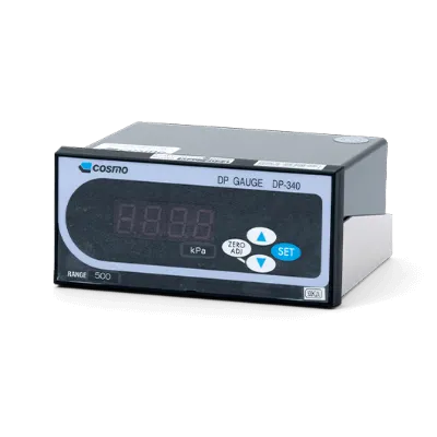
Multi-functional indicator
| Number of Channels | 10 channels |
|---|---|
| Upper and lower limit settings | 4 settings: HH, HI, LO, LL |
| Zero adjustment | One-push zero adjustment |
| Auto-zero | Auto-zero button |
| Display Hold | Hold button |
| Indicator response | Digital Filter (High, Medium, Low) |
| RS-232C | 1200, 9600 and 19200 bps switchable |
| BCD output | Open collector |
| Display digits | 3.5 digits (1999) / 4.5 digits (19999) switchable |
| Sampling rate | 250 ms / 50 ms switchable |
| User span | 0.001 to 9.999 (Default: 1.000) |
Documents
- * Please fill out the form to download.