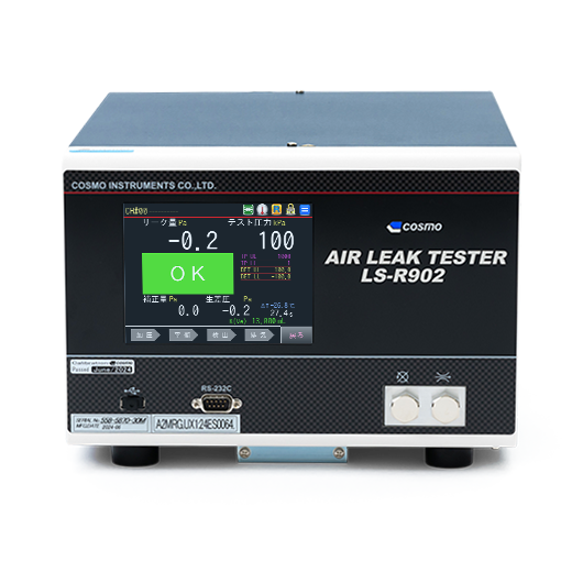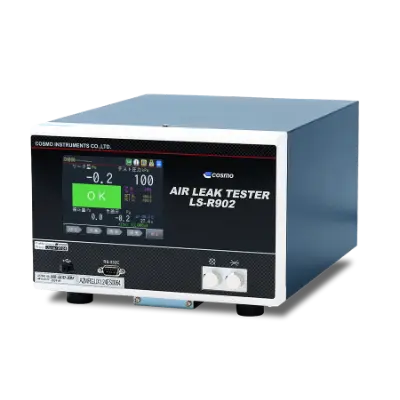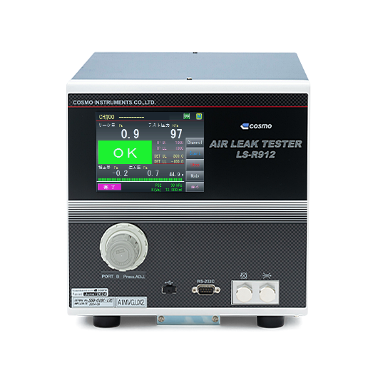
LS-R912 DP Leak Testers
- Color touch screen
- Two test pressure circuits switchable
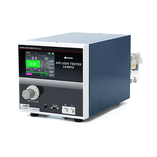
- Air Leak Tester with 2 Switchable Test Pressure Circuits
- Based on the specifications of LS-R902, two different pressure ranges can be combined with an E/P regulator or precision regulator. The test pressure will be automatically switched according to the work.
Basic Specs.
| Pressure range | -100 kPa to 4.9 MPa |
|---|---|
| Power source voltage | 100 to 240 VAC ±10%, 50/60 Hz, 80 VA max |
| Ambient temperature | Operating temperature: 5 to 45℃ Storage temperature: -20 to 60℃ |
| External dimensions | W263 x D412 x H275 (excluding protrusions) |
| Weight | Approx. 13.5 to 17.5 kg (depending on the spec.) |
Features / Functions
Select the combination of pressure ranges for the 2 circuits (Inlet A/Inlet B).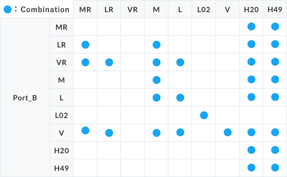
* E/P regulator code / MR: medium pressure / LR: low pressure / VR: vacuum
* Two pressure sensors for the higher pressure will be used.
- Measurement Performance Enhancing Features
-
-
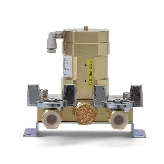
Intelligent Pneumatic Circuit
Leak detection circuit with internal pressure detection method, available in Intelligent 1 Pneumatic Circuit and Intelligent 2 Pneumatic Circuit. The differential pressure sensor and air operated valves are integrated with the manifold in a highly durable structure that minimizes breakdowns. In each test, the differential pressure sensor and the valves are self-checked to ensure that the judgment result is reliable.
-
High-performance differential pressure sensor
The improved differential pressure sensor, which is the heart of the Air Leak Tester, and the high-performance AD converter have realized measurement stability in units of 0.1 Pa. These effects are expected to improve measurement accuracy and shorten test time.
-
Mastering/Master Preset
Error components due to adiabatic compression, deformation, etc. during measurement are extracted and compensated using the value, enabling testing with a considerable error component, reducing measurement time and at the same time facilitating control on the master side. In addition, the system follows gradual environmental changes, such as room temperature, to achieve more stable measurements.
-
Leak calibratrion
To display differential pressure due to leak in flow units such as mL/min, a flow coefficient (Equivalent Internal Volume) is required. There are two methods to measure this coefficient: the volumetric change method and the Leak Master method. In addition, the fully-automated ALC (volumetric change method) and the automatic Leak Master provide the K-check function that not only measures the flow coefficient but also automatically checks for changes in leak sensitivity.
-
100 channels
Up to 100 channels can be set to handle a wide variety of works.
-
- Safety and Reliability Enhancing Features
-
-
Automatic setup
Allows the timers to be set automatically for initial adjustment.
-
Blockage Check
Memorizes the normal measurement status of secondary-side equipment and diagnoses whether external exhaust valves, switching valves, etc. are blocked.
-
Optimum Value Detection
Detects the change in differential pressure in Detection, which is the most stable and has the least noise, and converts it into a leak value.
-
Password setting
Allows users to change their password.
-
Manual valve monitoring
Automatically checks the opening and closing of the manual valves used for leak check of the tester itself. Detects if the valve(s) are left closed after a leak check, preventing leak testing with the valves closed.
-
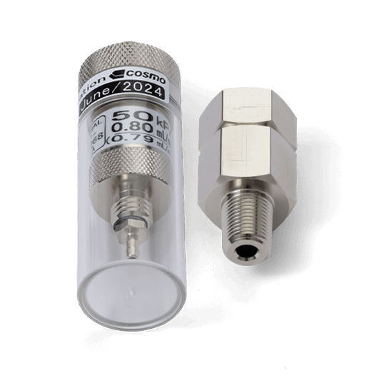
Calibration port
A port provided on the front panel for daily inspection and leak calibration. Differential pressure and test pressure can also be inspected and calibrated.
-
NR (Noise Reduction)
When the leak limit is lowered to pursue accuracy or to shorten measurement time, the ratio of noise to the measured value will increase. In the Noise Reduction (NR) mode, indeterminate judgment areas are set for the initial Detection, and if the work falls within one of these areas, the noise component is removed by repeating Detection so that false rejection of good works can be reduced.
-
External Exhaust Valve
To prevent malfunctions due to water or oil inside the works entering the tester, an externally installed exhaust valve (optional) is controlled by the tester.
-
Exhaust Interference Prevention
For a system with multiple leak testers, the exhaust process can cause large fluctuations in the source pressure. It can have a negative impact on the tester(s) that are still measuring. This function is provided to prevent this problem.
-
- Functions related to the interface
-
-
Color touch panel LCD
Easy-to-understand large color touch panel LCD allows intuitive operation.
-
USB memory data storage
A USB memory can be used to store large amounts of data for long periods of time, and data can be easily transferred to a PC.
-
Multilingual
Allows you to switch the display between multiple languages, including Japanese, English, and Chinese.
-
I/O monitor
Check the connection of the signals with external PLCs, such as start/stop signals and pass/fail signals, on the screen. This is very useful when equipment is connected.
-
Quality management
The latest 1000 work data (5000 for LS-R902) can be stored and displayed in a graph, which is useful for monitoring changes in work characteristics and changes in the measurement environment. In addition, the Mastering characteristic graph makes it easier to set test conditions.
-
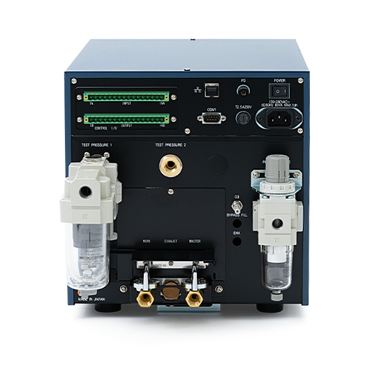
- Pneumatic Circuit
-
-
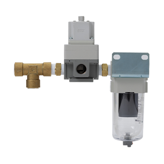
Test pressure 2-circuit switching
Allows the tester to switch between two test pressure circuits using the combination of a precision regulator and an E/P regulator.
-
Test pressure control by electro-pneumatic regulator
Test pressure is remotely controlled by an E/P regulator. Different settings for each channel and high-speed charging are possible.
-
Bypass circuit
To reduce pressurization time for large-volume works, the tester directly controls the valve of an externally installed bypass circuit unit (optional).
-
High-pressure compatible
Supports leak testing at test pressures in excess of 1 MPa.
-
Documents
- * Please fill out the form to download.